
Our buildings contain a wide range of technology, from the most basic to the most complex, and therefore operate in a different way to the average building. All temperatures are measured and recorded for future study, for a period of up to one year. We also measure carbon dioxide levels in the air in many lecture halls, conference rooms and group rooms, and increase ventilation as needed. This means that most rooms operate best with the doors and windows closed, to ensure that air follows the “right path” and passes over the sensors that are set up to measure temperature and air quality. This ensures that we can maintain the ideal temperature and best air quality. It also means that the number of people in a room should not exceed the number it is furnished for. All teaching rooms at the university are specified to meet AQ2 air quality requirements. This means that the average measured carbon dioxide level over a one-hour period should not exceed 1,000 ppm.
Some basic facts
Vi kyler våra hus på det miljövänligaste sätt som går, enkelt utryckt med Vättervatten. Det är en ledning som We cool our buildings in the most environmentally friendly way possible, using water from Lake Vättern. A conduit runs out 2,500 metres into Lake Vättern, to a depth of 65 metres. The water passes through a heat exchanger, which cools the water that is circulated around HÖFAB properties, among others, to provide cooling.
Our computerised control and monitoring system controls and monitors all air conditioning units, heating systems, cooling systems, teaching rooms, group rooms and conference rooms. To ensure that the automated system in the controlled rooms operates correctly, doors and windows must be closed, otherwise the air quality and temperature sensors give inaccurate readings.
We control the temperature and air quality in each room that accommodates six or more people, so that when you are in our buildings you remain as comfortable as possible, and rental costs are optimised for our tenant.
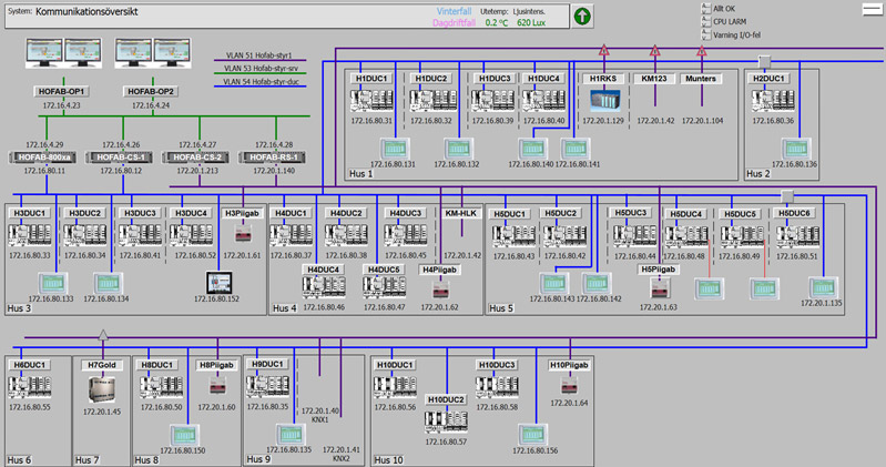
Our control and regulation installation currently consists of a distributed control system (DCS) based on an ABB System 800xA platform that is closely integrated with 26 ABB AC800M controllers. We also have some other equipment that is linked by SCADA to the System 800xA, see below.
- SIEMENS Simatic S7-300
- Water meters and energy meters, M-bus.
- Swegon Gold ventilation unit
- Munters ventilation unit, Modbus
All our air conditioning units and most pumps are speed controlled. (We do not circulate more air than is needed to meet ventilation, cooling and heating needs).
We control the lighting in public areas, lecture halls, group rooms and conference rooms using the KNX building control standard. We have one of the largest KNX lighting systems in Sweden.
We have approximately: 345 card readers for entrance control.
We have approximately 570 kilometres of electric wiring and around 510 kilometres of data cable in our properties.
We have 34 air conditioning units that supply the buildings with air.
Art in the buildings
Control and monitoring
At HÖFAB we have thoroughly reviewed requirements and carried out a complete upgrade of the initial control and regulation system that was installed when phase 1 was built. Phase 1 includes building B (IHH, JIBS), building C (the University Library), building E (JTH) and parts of building D (Students’ Union).
The main reason for this decision was that replacements for the existing digital controllers that managed the heating, cooling and ventilation systems in the buildings were no longer available. We also decided that the ventilation in all rooms that can accommodate more than four people should be controlled based on demand. The decision was also taken to switch from SCADA to a distributed control system (DCS). Our choice was ABB System 800 xA with ABB AC800M controllers, as this allows us to use the existing input and output cards in the installations. The ABB System 800xA is also connected to other existing control systems and then operates as a SCADA system.
The experience we had gained from 14 years of operating the control system meant we were able draw up new guidelines for how we want the ventilation system to work. The most usual way to design a ventilation system is to use a single pressure control unit for supply air and another for extract air. Our experience told us that this led to a waste of energy. So we now use individual pressure control for the supply air and extract air on each floor. This gives us superior control over the flow of air.
Before we rebuilt the control system, all the fans ran at full speed and a little more to achieve the prescribed extraction rates for all areas in the buildings. By using pressure controls on each floor, the pressure sensors that control the fans are now able to detect the pressure change that occurs when there is a change in demand from a room controller. The diagram below shows the operation of the fans over the course of a day in one of the installations that was upgraded.
If you have any questions about the installation or our experiences, email Mikael Falk.
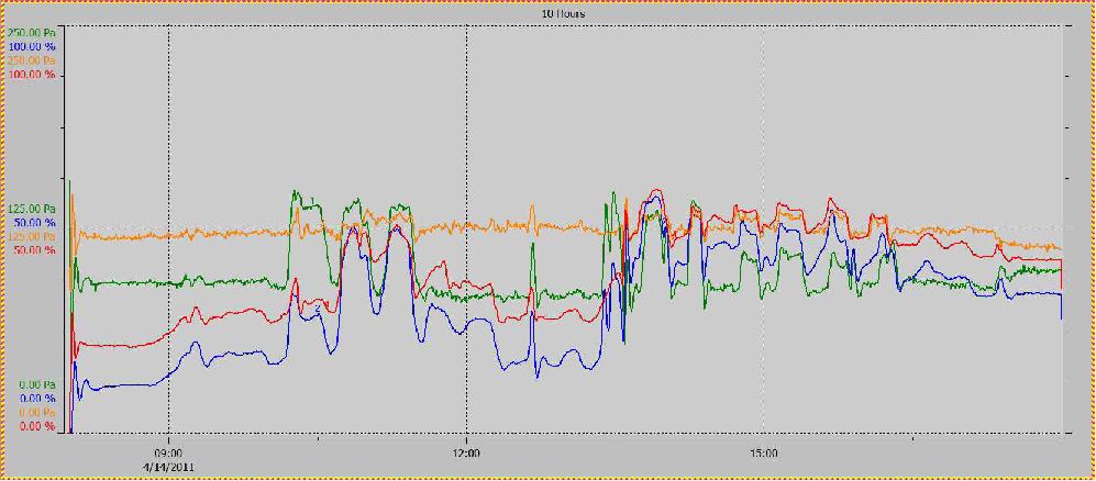
The blue line is the supply air fan and the red line is the extract fan. The green line is the supply air pressure and the orange line is the extract air pressure. Every change in the air demand for the installation can be seen as a fluctuation in the lines.